3D Printer so far. Can’t print anything yet!
In this post I attempt to describe how I attach the stepper motors on the X and Y axis, and how I’ve started mounting the lead screw for the X-axis.
For this post to make any sense at all, I will have to show how the X-Y table works (10 second video):
So the job here was mostly to attach the motors to the X-Y table somehow, and then attach the lead screws, bearings etc afterwards. Having a look at the X-Y table, there are already one ~15mm hole with set screws for each axis. Since the stepper motors won’t fit in these holes directly, I created a couple of adapters by turning aluminium.
-
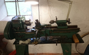
- Lucky me who has access to this machine!

-
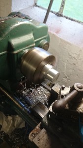
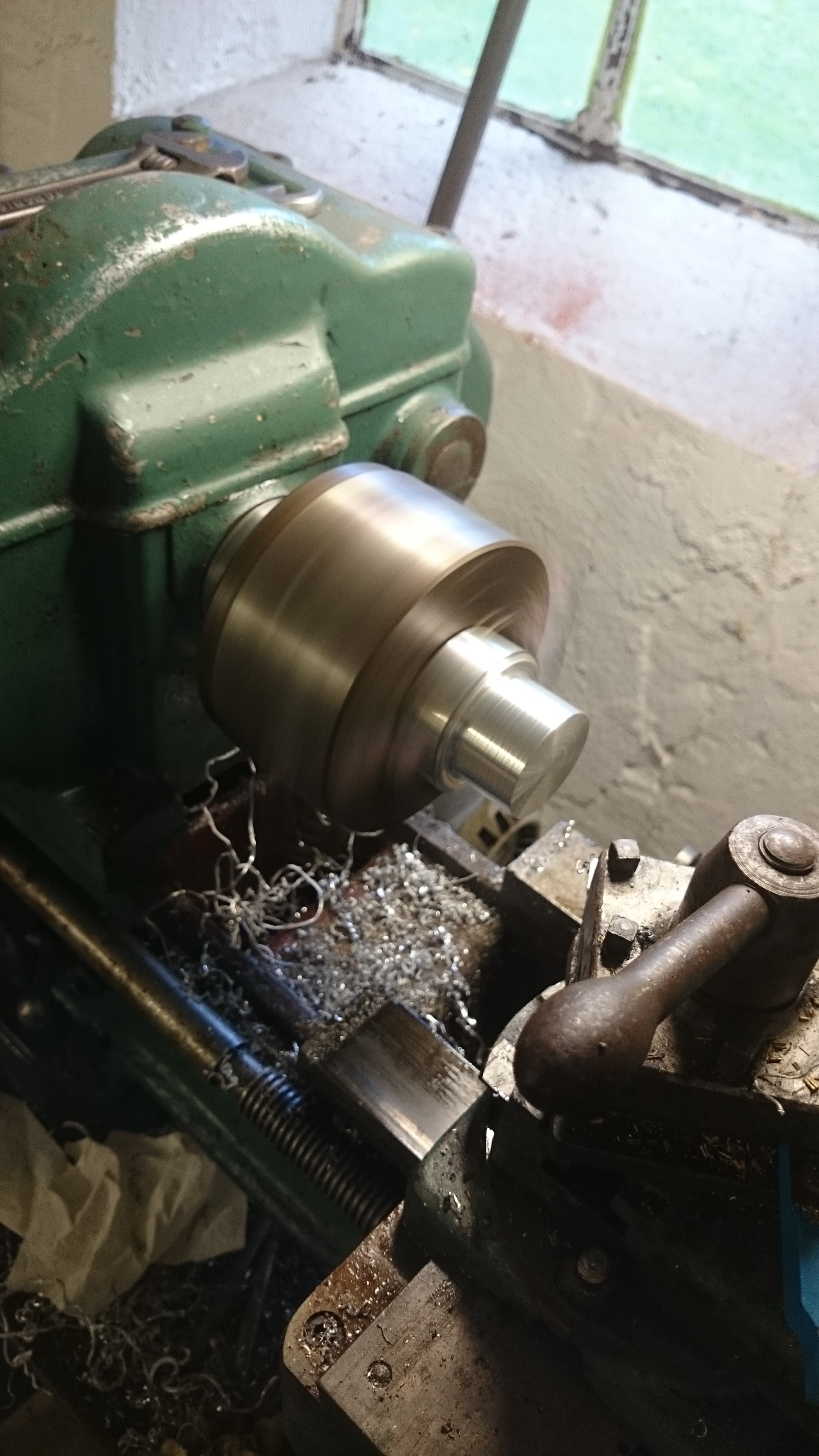
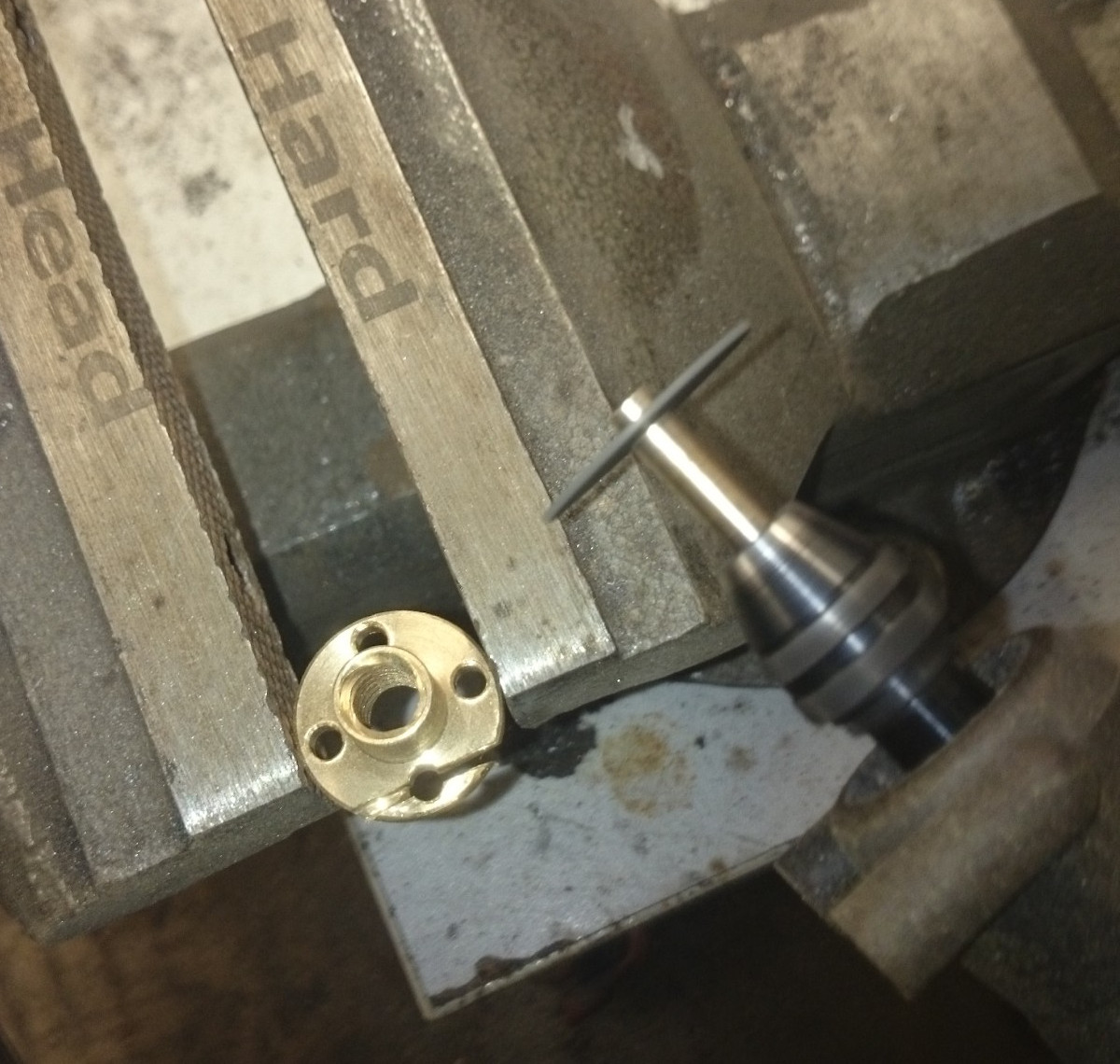
- Started with a massive cylinder of aluminium. Turning one end to be smaller and smaller
-
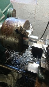
- Almost done turning!

-
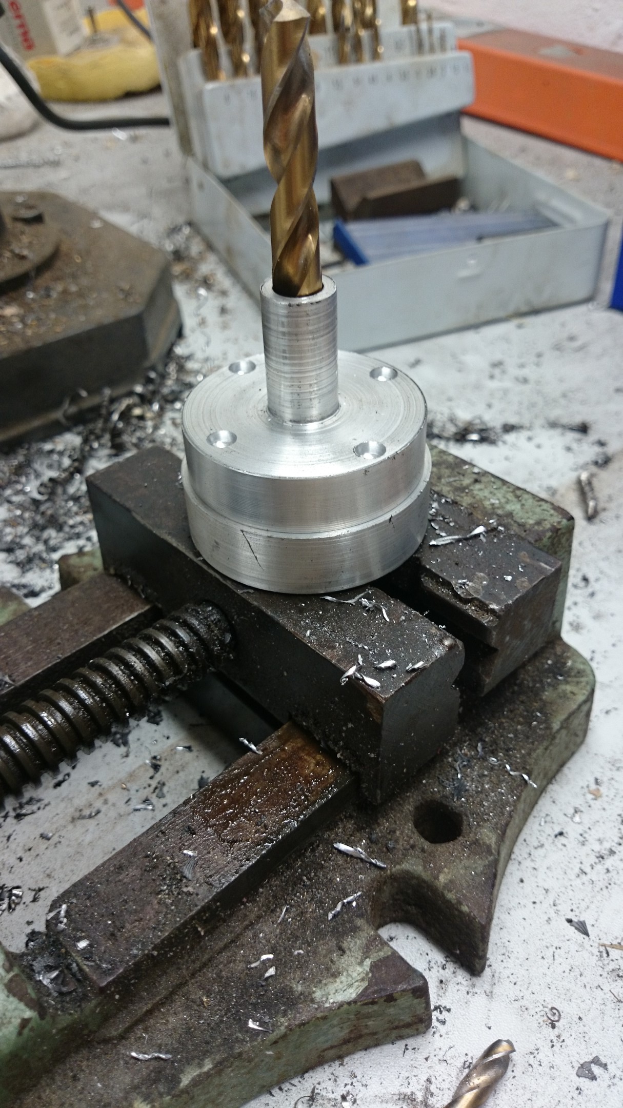
- Copying holes from one piece to the other. The bore is used to align them perfectly on top of each other.
-
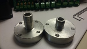
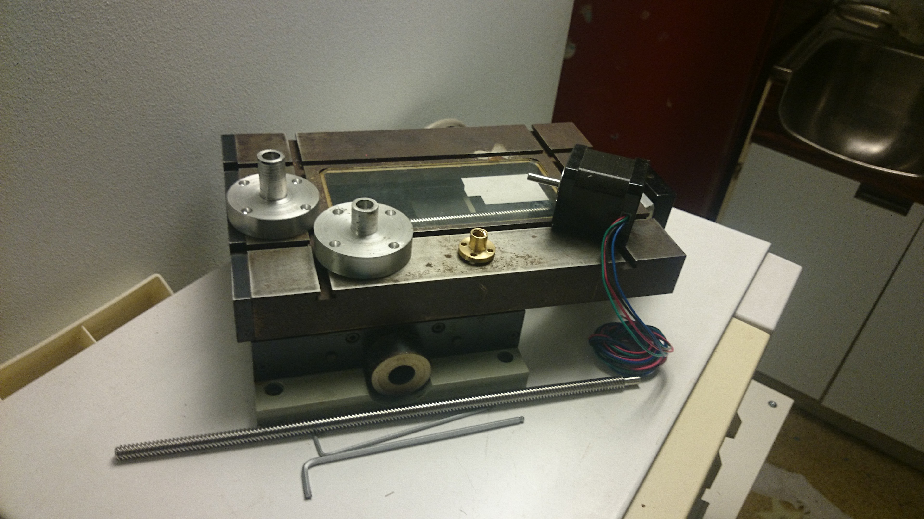
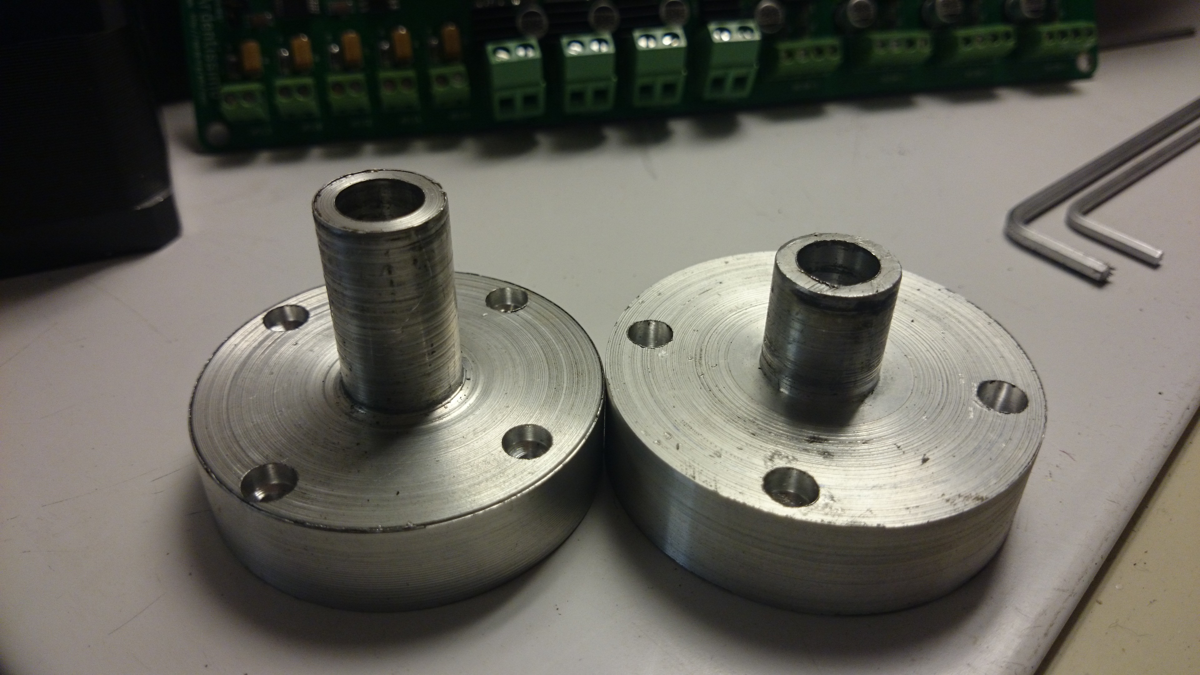
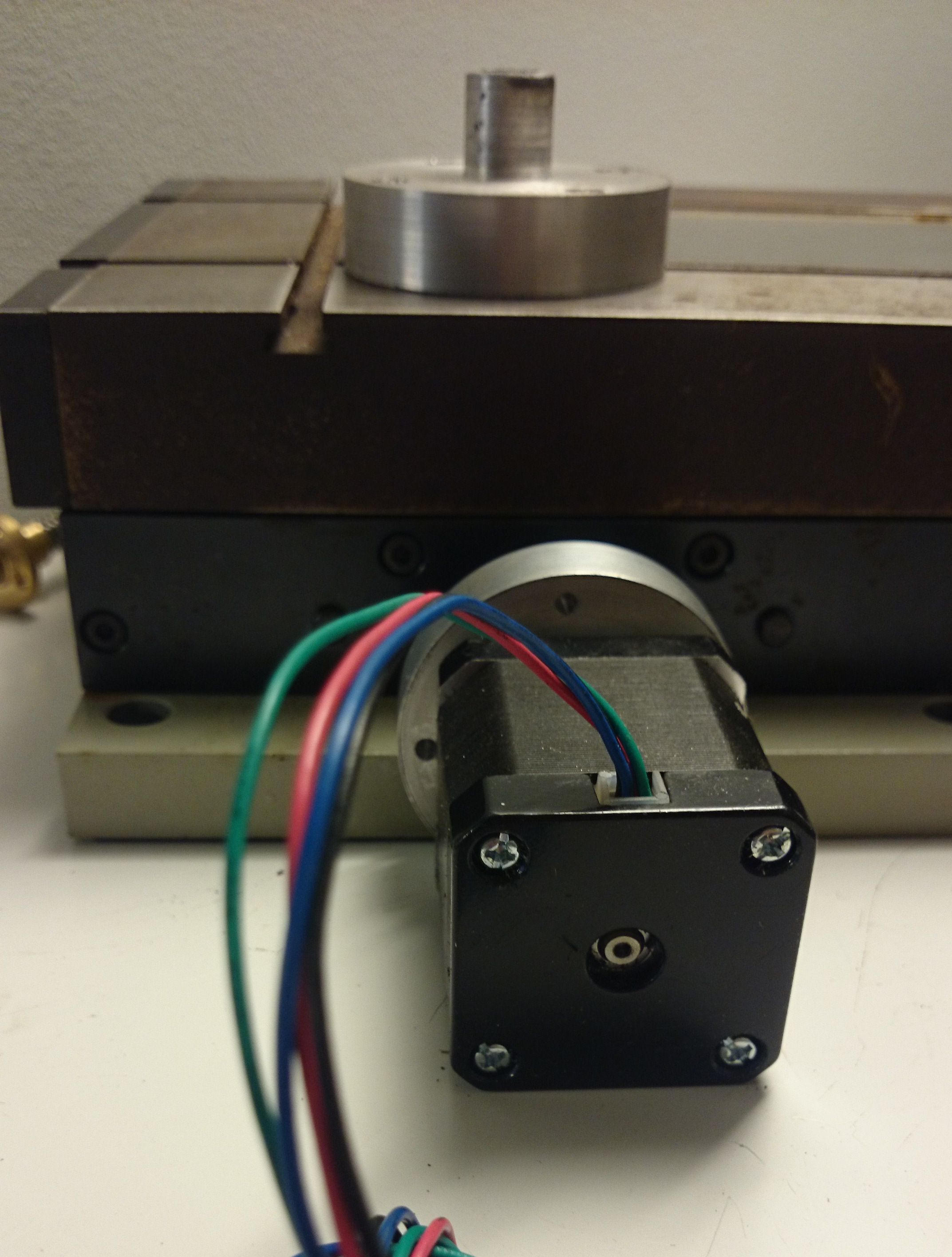
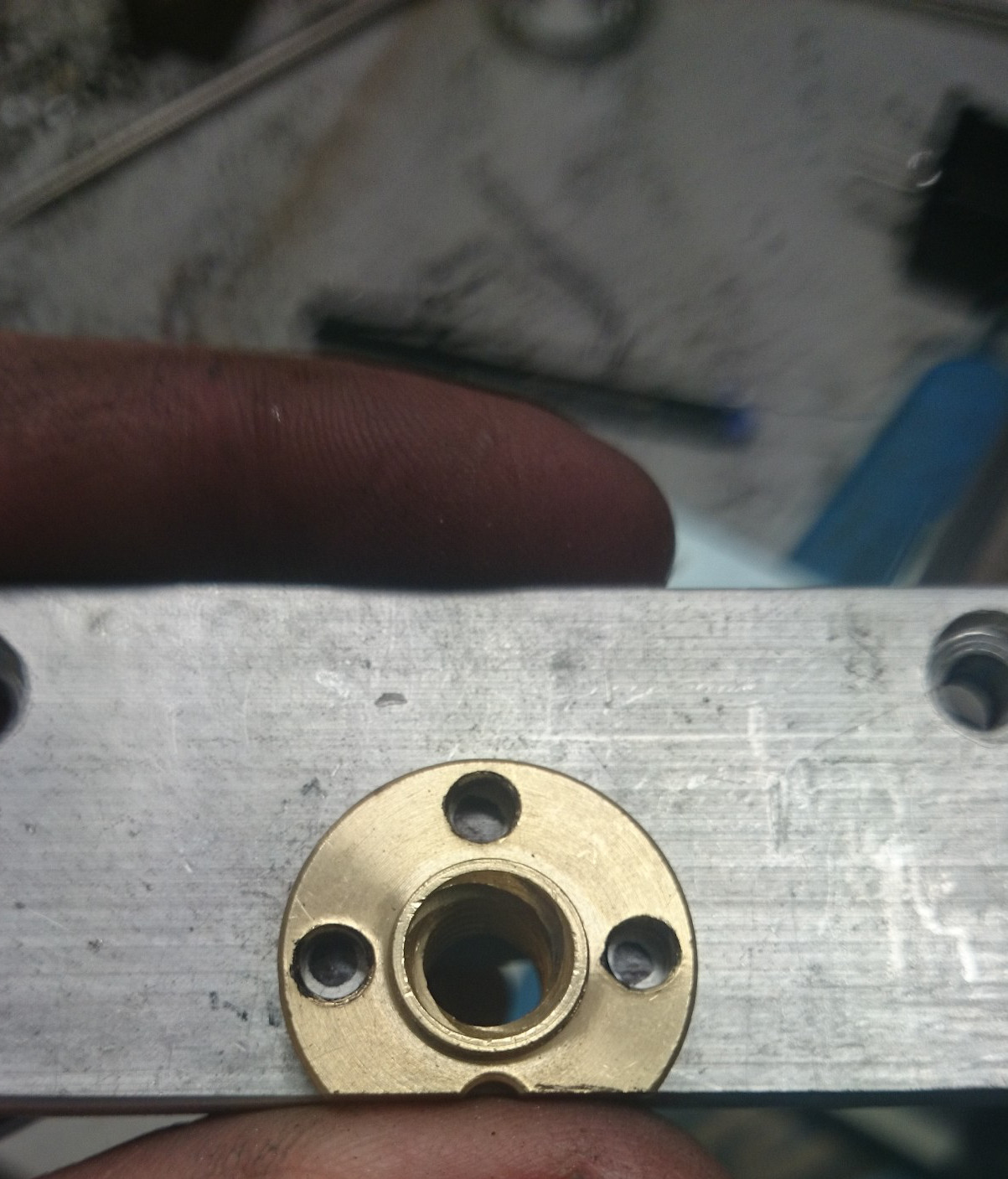
- Two finished adapters, one for each axis. This piece fits the stepper motor on the back side and X-Y table on the top. The four screw holes fits in the motor. The thin end fits into the hole of the X-Y table. The rotating shaft of the stepper motor will come out of the hole in the middle.
-
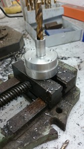
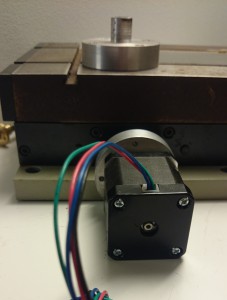
- There it goes

-
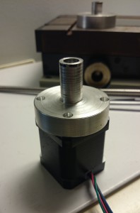
- The adapter now fits on the stepper motor

-
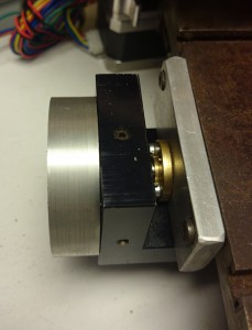
- The adapter and stepper motor now fits in the X-Y table
-
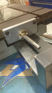
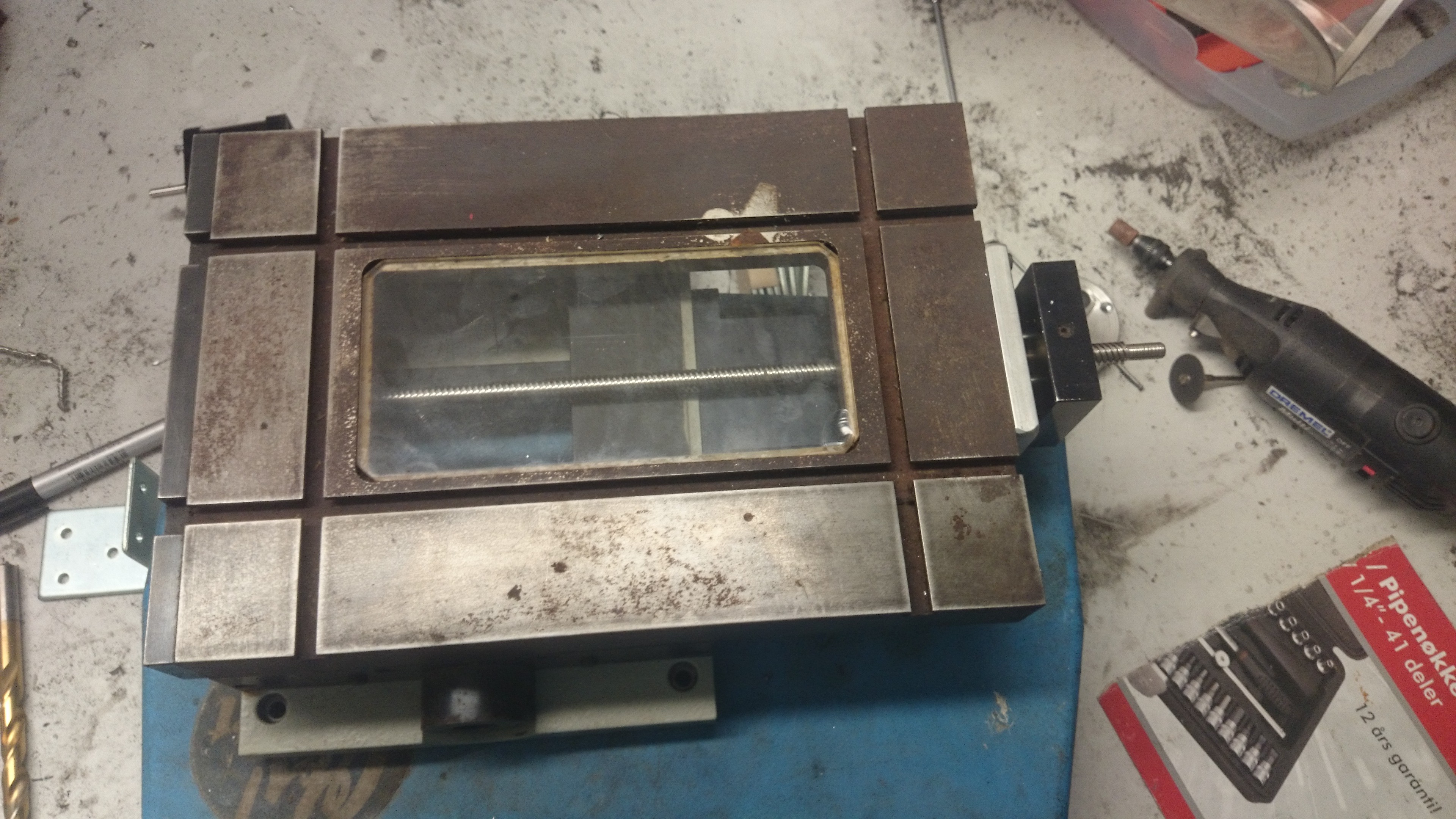
- This is how the lead screw is mounted to the X-axis. I had to create the aluminium piece to fit the existing screw holes. I bought the lead screw and nut, and had to make some adjustments to them.

-
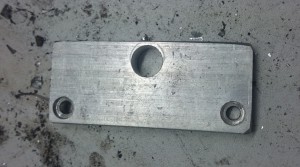
- This is the aluminium piece, ready with a hole for the nut

-
- Oh, this will not fit. Time to use the dremel!

-

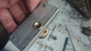
- Fitting the nut
-

- Nut fitted.
-

- The X-axis is almost ready
-

- 3D Printer so far. Can’t print anything yet!
-
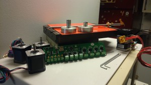
- Just sitting there waiting to be finished!
