
The electronic sheep is a plastic sheep fitted with a rgb-led inside. It can show colors in various patterns, and the electronics also supports adding a servo motor for moving the head. I will describe the works and making of the electronics and code. This is a good beginners project for using an Atmel microcontroller.
Electronics
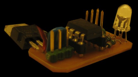
An AVR ATtiny85 was used for controlling the LED. A 3-pin header is added to support a 9 gram RC servo, which will be controlled by a ppm signal. A 9v battery gives power to the circuit trough a 7805 voltage regulator. This is old fashioned, as the 7805 pack is known to be ineffective and produce heat. On the other hand, it is simple and cheap. The LED is a 4 pin with common cathode. This means that it has to be sourced by the microcontroller, a shame since it has to provide more current that way.
A single side board was designed in Eagle, download the files in the download section or just look at the picture:

The finished board:
– Choose carefully between routing at the top or bottom layer. When routing for surface mounted chips, the top layer is good. When combining, use the bottom layer and invert the surface chips footprints.
– If you are milling the bottom layer, you have to be drilling the bottom layer as well.
– Reuse all older cards. There is no use to make a new ISP-header when you already have one from another project that you know works.
– It pays off to print the board in black and white, and then see if everything fits together correctly.
– Use thick wires for areas where there will be high currents
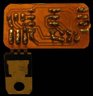
The card was milled using a CNC machine with a ~1mm thick cutter tip and a precision of 0.03mm.
The code
The code is split into modules for the different tasks. The rgbsheep.c file contains the main() function, and uses functions from servo.h and rgb.h. The larslib.h is only included to add the necessary avr libraries.
RGB
Based on 24-bit colors, the amount of red, green and blue can be specified using three bytes, where 0 is minimum and 255 is maximum light. This is achieved using PWM on the output pins within the rgb_ISR() function. For each interrupt, the t variable is incremented. The different LED-colors will be active for as many interrupt calls as specified in the r, g and b variables, from a total number of 255.
A natural way to program this would be to use an overflow interrupt. The inbuilt timer would count 255 CPU cycles before calling the specified function. This function would then count the 255 steps for the LED, sorting which to be on and off. The problem is that since the mcu runs with 1Mhz, the rate of the PWM signal on the LED would be:
1000000Hz / (255*255) = 15.38Hz
The human eye needs at least 60Hz not to see the flickering. To get a higher rate for the PWM, the comparator interrupt is used instead.The OCR0A value tells how many cycles the processor is allowed to run between each interrupt call, and is set to 30 insteaf of the previous 255.
1000000Hz / (30*255) = 130.72Hz
This is fast enough to look smooth for the eyes, but the flickering can be seen when using a camera, as in the video above.
Servo
servo_init() activates the comparator interrupt vector for timer1 on the tiny85. To be added later.
Future work
The servo is not yet included. It is added in the hardware, but did not have much space inside the sheeps head, and was left out. It was tested by some quick dirty code, and seemed to work fine.
The rgb-led could be replaced by another one with common anode instead of cathode. The only difference on the PCB would be to make the fourth LED-pin 5v instead of ground, and to invert the pin logics in the c-code. This would take some load of the microcontroller.
The sheep would be even cooler if it had more LEDs troughout its body, but it would require a bigger microcontroller with a bigger PCB. One could also connect several LEDs to the same pins.
A buzzer could make the sheep beep for attention.