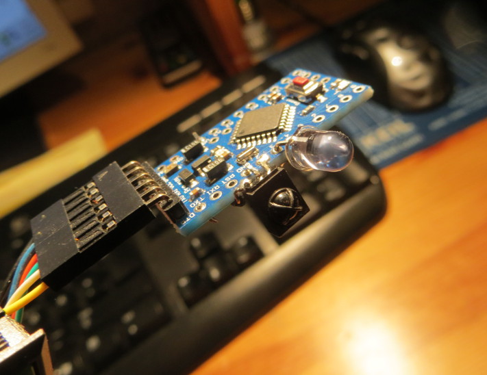
This is an IR transmitter / receiver circuit I’ve made to control my TV, amplifier etc from my computer. It was made using a cheap Arduino clone, an IR module and an IR LED. The receiver can read most infrared remote controllers, independent of which protocol they may use.
Parts list
- Arduino
- 100 Ω resistor
- IR LED
- 38 kHz IR Module
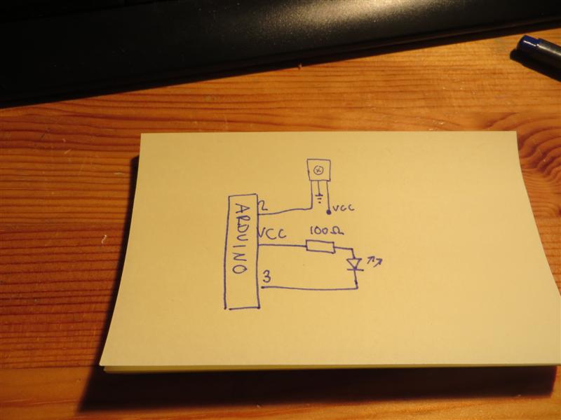 The IR LED is sinked, meaning it will go bright when digital output 3 is cleared.
[notice]Note that it would be nicer to the Arduino to add a transistor on the LED pin, to draw less current from the microcontroller.[/notice]
Receiver
The receiver constantly listens to the IR Module, and outputs a comma separated string to the UART whenever a signal has been received. The string starts with a zero and ends with 65535. The rest of the buffer is also written, but should contain only zeros and can be ignored. Arduino output example:
0,128,95,208,232,103,117,103,117,103,117,65535,0,0,0,0,0,0,0,0,0,0,0 … etc
The red digits are only useful for debugging.
The code works by listening to an external interrupt on the pin connected to the IR module. The interrupt triggers on pin changes, and stores the number of timer tics between each pin change. The signal is presumed finished when the timer has stored 20 overflows.
Transmitter
The IR Transmitter takes the output of the IR Receiver as input to the UART. A valid input text would be:
0,125,99,230,218,115,65535
These values can be between 1 and 65534, and have to start with a 0 and end with a 65535. I didn’t use a newline character at the end of the string, but I don’t think it will make much difference. If the IR receiver has been given a valid IR code, it should output something like:
…….Thanks. I got: 0,125,99,230,218,115,0,0,0,0,0,0,0,0,0,0,0,0,0,0, – Length: 6
This is one ‘.’ per byte received, and then the 20 first bytes of the received buffer after parsing. A maximum of 127 pulses can be sent.
ir_send will send the current contents of the pulse.data buffer. If a pulse is longer than the period of the 8-bit timer (>255), the remaining time is divided into timer overflow interrupt calls (periods of 255 timer tics).
A timer compare match interrupt adds a 38kHz pulse to the high pulses. This is toggled by activating and deactivating the interrupt in the TIMSK register, done inside the setKhzActive function. To generate a 38 kHz pulse using a 16MHz crystal:
16000000 / 38000 = 421 tics/period
Since we have two pin changes per period, we get
421 / 2 = 210 tics/pin change
Then measuring and tweaking gave 210 → 181
OCR1AL = 181; // 37kHz
Future work
A text string from the receiver code can be used as input to the transmitter code. The plan is to store codes for the most used remote controls in a text file on my computer, and then make a program that can output these values to the transmitter automatically.
Downloads
Arduino Transmitter Sketch
Arduino Receiver Sketch