I needed a servo tester for my workshop, to have at hand whenever I change servo horns or need to see if a servo is dead. I decided to use a 555 timer to do this.
Driving a servo
This is covered everywhere on the internet, so I’ll be brief. A typical RC servo is controlled by a 50Hz square pulse signal called Pulse Width Modulation (PWM). The high pulse time varies from 1ms to 2ms, where 1ms gives 0 degrees and 2ms gives 90 degrees. This is followed by a low time of 16-18ms.
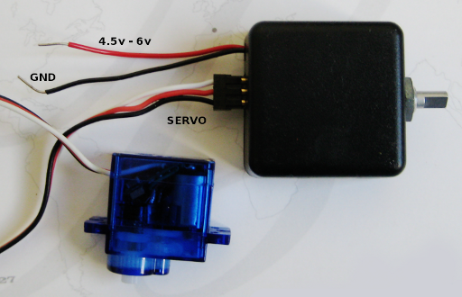
The servo has a three pin 0.1″ connector with the following pinout:
RED – +4.5v to 6.5v
BLACK – Ground
WHITE/YELLOW – PWM Signal
Implementation
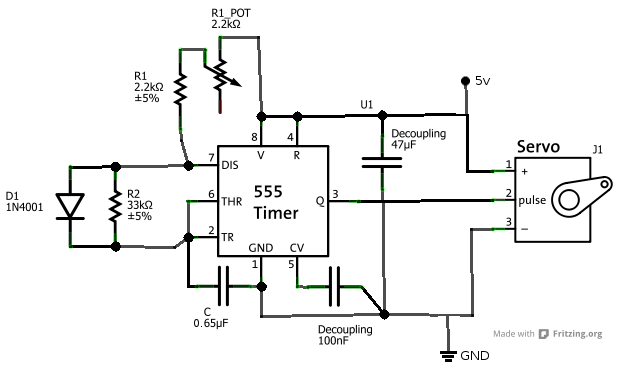
In order to have a low time that is longer than the high time, it it is necessary to put a diode over R2, in a configuration called extended duty cycle astable. Thus, the schematic becomes:
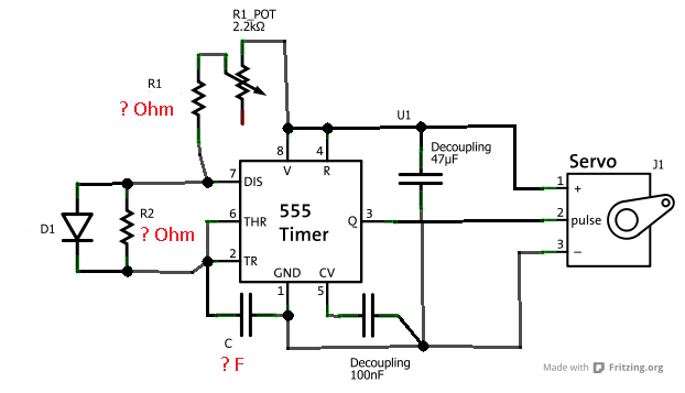
We need to use maths to solve for R1, R2 and C.
With the diode in place, the formula is given as:
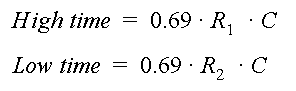
The potmeter regulates between 1ms and 2ms for the high pulse, so it follows that 2200 Ohm corresponds to one millisecond. The high pulse should never be under 1ms long, so we need an 2.2kOhm resistor in series with the potmeter. This is the value for R1 in the schematics. When the potmeter is fully on, we have 4.4 kOhm and a 2ms high pulse. Knowing this, we can solve for the capacitor value C:
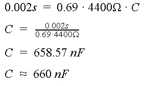
Since we know that we need 2200 Ohm per millisecond, we can simply say that
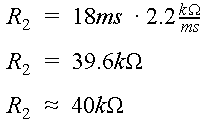
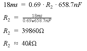
Or, if we want to do things the hard way, we insert our capacitor value into the formula to solve for R2:
To verify this, I had a look at the graph in the 555 timer datasheet, knowing now that R1+R2 = 44kOhm.
TLC555CP (555 timer)
8-pin solder tail DIP (socket)
2.2kOhm potmeter (R1_pot)
2.2kOhm resistor (R1)
33kOhm resistor (R2)
500nF capacitor (C)
150nF capacitor (C)
100nF capacitor (decoupling)
47uF capacitor (decoupling)
3-way male 0.1″ pin connector (servo connector)
Filling in all values, the schematic now looks as follows:
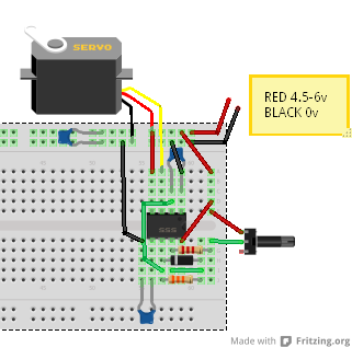
 I tested Fritzing, a simplified electronics layout editor for hobbyists. I still prefer Eagle, but at least it is cool to be able to show the circuit as it would be on a bread board:
Conclusion
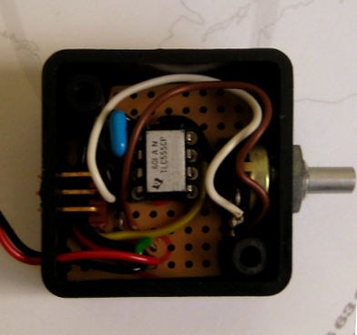
Before making this writeup, I’ve already put the servo tester to good use. It comes in handy more often than I had planned, and is very good to have as a reference whenever I code something that uses a servo.
Downloads
Further reading
555 Timer
555 Timer datasheet
Wikipedia – Servo Control
Servo control
Servo tester by 555 timer
Fritzing
3 comments
Very interesting circuit, but it sure would be nice if you indicated on your circuit diagram where PLUS and NEG are fed in from the power supply. I could work it out from the breadboard wiring, but the schematic should really show where they are applied.
Your schematic is wrong, the value of C is 680nF, or 0.68uF. You placed in the drawing “65uF”.
Author
Hey Bob and Eduardo! You are both right, so I’ve updated the schematic.
Eduardo: For the convenience, I made my circuit by combining a 150nF and a 500nF capacitor in parallel, so I updated the schematics to be 0.65uF. 65uF was completely wrong. Thanks for pointing this out for me!