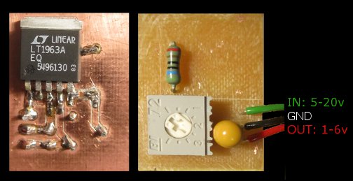
I came across this Low DropOut voltage chip and figured I would use it as an adjustable voltage source. All it required was a trimpot, a capacitor and a resistor.
Parts
LT1963A low dropout voltage regulator
10uF ceramic capacitor
560 Ohm resistor
2200 Ohm trimpot
Using the LDO
The chosen LDO has an input voltage range of 1.9 to 20v, and can output between 1.17 and 20v. It can give a maximum of 1.5 ampere, with a dropout voltage of 0.35v. It also has reverse current protection (see datasheet), useful for careless lab experiments.
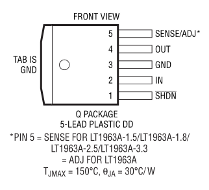
ADJ – The pin which decides what voltage to put on the out pin
OUT – The output voltage
GND – Ground pin 0v
IN – The voltage input, from 1.9 to 20v
SHDN – Shutdown, to send 0v on the out pin when pulled low. Can be controlled by 5v logic or be disabled by connecting to IN pin.
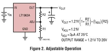
The datasheet gives an example circuit for adjustable operation, and a formula for choosing the right resistor sizes.
The maths
The original formula from the datasheet gives that

As I is very small, I ignore it to make the maths easier

In order to limit the maximum voltage, R2 is made a trimpot. If I had used R1 for this, I would limit the minimum voltage, and the trimpot would start at the highest voltage and twist downwards. The easiest is to regulate R2, so I used a 2.2kOhm trimpot for that. If I want the voltage range to start at a higher voltage than 1.21v, I would have to add a resistor in series with the trimpot. I need the voltage to be between 1.21v and 6v, thus leaving R1 as the unknown:

With an E-series 560 ohms resistor, feeding everything back into the original equation, my max output voltage will be:

Electronics
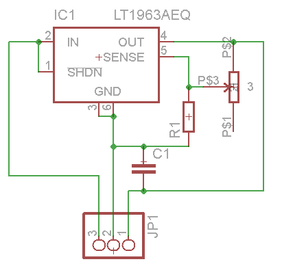
I’ve used through-hole components for this build. The schematics is not much more complicated than the example circuit from the datasheet, only replacing R2 by a potmeter. I had to make the potmeter in eagle, as I could not find any specifications or premade potmeter libraries. I chose to connect SHDN to IN, in order to disable the shutdown functionality that I won’t be needing.
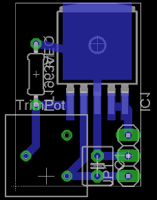
I made the board as one layered and printed it using a CNC mill.
Conclusion
When twisting the trimpot, the voltage goes from 1.2v to 5.97v linearly. I intend to use this to test LEDs, drive motors and such. I will also use this as a 3.3v supply for microcontrollers, as I only have a 5v cell phone charger available at the moment.
A way to improve this project would be to use a potmeter with a proper nob, and put everything in a nice encasing. It would be useful to have something to indicate the output voltage, for instance a LED bar.